backchannel: thoughts on the “real numbers” DC-DC video
This post refers to “I Show REAL Numbers: Impact of DC-DC Chargers from DJI, EcoFlow, Bluetti on Alternator” on Youtube.
TL;DR
As we already knew:
- size the DC-DC to your alternator and bank
- don’t idle to charge
some things to keep in mind
- the F-terminal signal he’s observing is the signal voltage to the Field winding, which is used to regulate alternator output. We might think of this as “the gas pedal” of the alternator. The amount of pedal input required to hold a given speed varies based on the situation (uphill, downhill, headwinds, etc). Instead of holding a certain MPH the field is energized to hold a certain voltage.
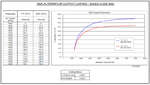 Alternator output capacity varies at different alternator RPM. The output curve for my 180A alt is thumbnailed on the right.
-
because of pulley ratios the alternator RPM and engine RPM are generally in a 3:1 ratio. Example; if the engine is spinning at 750RPM then the alternator is spinning ~2,250RPM.
- the percentage of utilization (amount of “throttle” applied) is only indirectly related to alternator harm. The real problem is heat. With heat monitoring (like with a Balmar, Wakespeed, etc external regulator) the alternator can be safely run at 100% field indefinitely. Field strength is one variable to consider, along with ambient temps, airflow across the alt, etc.
- the poster is under the mistaken belief that the alternator can be run at the rated output constantly without heroic approaches like the external regulators referenced above

the video
the truck before charging
3:15 His truck has a 170A alternator. Chassis voltage varies 14.0v - 14.2v for the most part.
4:30 While driving with normal vehicle loads the field is ~27%.
5:04 idling at a stoplight the field is ~48%. The alternator is still able to output normal voltage.
7:00 driving again; turning on many accessories in the vehicle increases demand so field strength rises from ~27% to ~43%,
charging
Note: by the time he activates the charger the chassis voltage has dropped to 13.2v. When he activates charging it starts rising again in response.
 He is running a DJI Power 1000w Super Fast Car Charger.
The manual (pdf) states a 70A max output (1000w / 70A = 14.29v). It is not clear from the marketing or documentation that it can be derated by the user.
At 9:05 he observed 1,064w of charging and field strength at 54%. I think that’s acceptable.
11:40 By the time he approaches a stop the chassis voltage has risen to 14.4v. Stopping at the intersection means the engine RPM is reduced, so the alternator RPM is reduced and output at that field strength plummets:
[stopped in traffic] “we’re at 93% and we’re still charging at over 1000w”.
It’s at 93% because he’s charging at 1000w while sitting still. The field strength % goes into “pedal to the metal” territory attempting to hold the voltage setpoint; it can’t. Voltage drops to ~13.8v and the alt is being hammered. Luckily traffic started moving again and he could spin up the alt.
worst case scenario
 That stop is a confluence of Bad Things:
- at stop the alt fans aren’t spinning fast enough for good cooling
- and is sitting in a hot engine bay so any cooling air is already heated
- at low RPM where alt efficiency is low (1000w of charging means >1000w of heat)
- and the alt is pinned to the wall by demand
This is how we damage alternators.
in my opinion
I would use the field strength % at highway speeds to observe what charge rate results in a 50% field. Then I’d do the same at idle. If the charger can be derated I would use those settings as defaults depending on if I were traveling or driving in the city.
comments
mastodon comment thread for this post
lemmy comment thread for this post