280Ah finally full
charging goals accomplished
- charged to 13.8v, Absorped until acceptance dropped to 14A (0.05C)
- cell imbalance 3mV in just before the transition to float
- both the BMS and shunt read 100% SoC
trying for the middle 80%
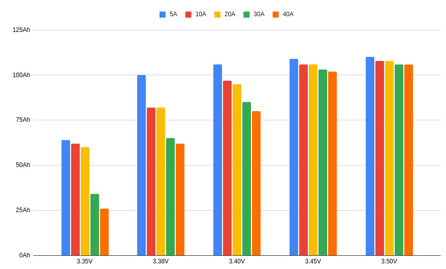 The chart on the right is Off-Grid Garage’s capacity testing charging at different C-rates and Vabs with zero minutes of absorption (charge-and-stop).
The problem we have with solar charging is that it is inconsistent. A 20A power supply would yield predictable results since the C-rate would be constant. Solar’s charging rate will be all over the place. The most I can shovel into the bank is ~50A, or 0.178C. Using the chart and assuming 0.1C (28A) we get
- 13.60v @ 0.1C = ~90% SoC
- 13.52v @ 0.1C = ~80% SoC
- 13.40v @ 0.1C = ~67% SoC
pseudo-Equalization
I have an “equalization” voltage of 14.0v defined, terminated by voltage. This will run 1x/week to reset the SoC counters.
experiments
initial setup July 23
13.6v, absorb until acceptance drops to 0.05C. This will likely be very near 100%.
July 24, first full day with new settings
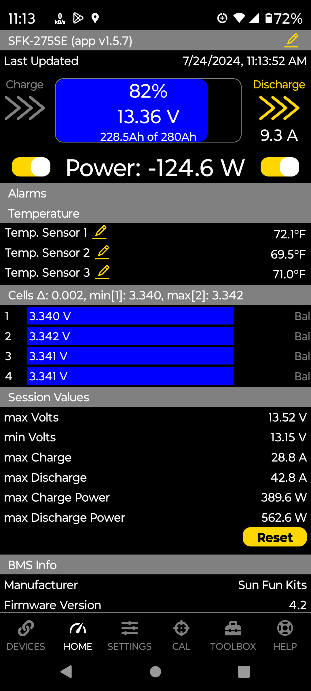 First attempt went well; Absorping at 13.6v until 0,05C (about 50 minutes under these conditions) brought us to 82% SoC.
The 13.3v float works well when charging fully but doesn’t quite hold SOC when charging below 100%. I increased Vfloat to 13.4v and SoC has stopped dropping at 79%.
Note: in the screenshot the controllers had just transitioned to float so voltage was falling.
Update 1830: bank stayed ~80% throughout the day.
July 27
temperature monitoring
![]() I mounted the battery warmer temp probe and the Smart BatterySense on the narrow edge of the battery case. It reads several degrees off what the BMS’s cell temp probes read. I think what’s happening is the case was built to accommodate 304Ah cells and is shimmed on the edges when used with 280Ah cells (see inset image).
I mounted the battery warmer temp probe and the Smart BatterySense on the narrow edge of the battery case. It reads several degrees off what the BMS’s cell temp probes read. I think what’s happening is the case was built to accommodate 304Ah cells and is shimmed on the edges when used with 280Ah cells (see inset image).
I moved the probe1 to the long side during the next step.
foam box

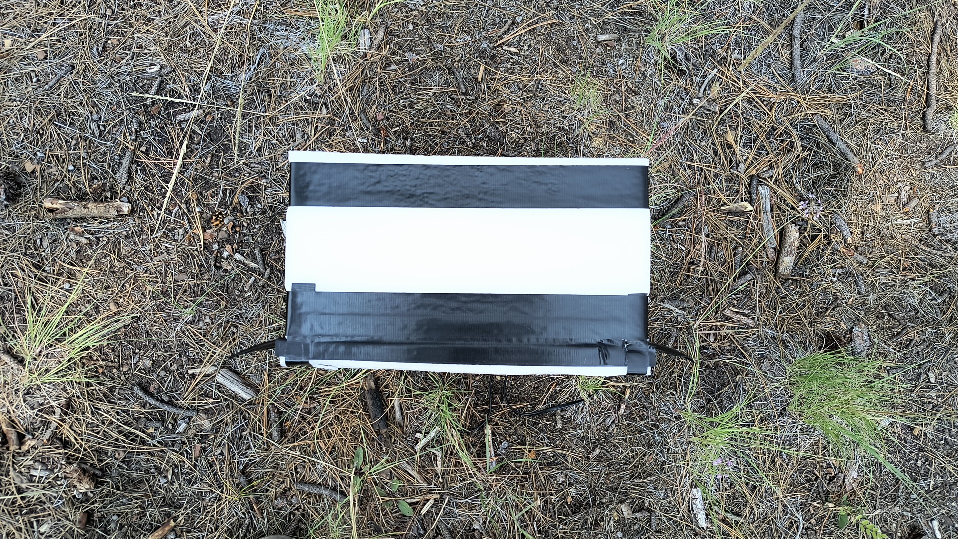
I was satisfied the SFK was working fine and so wanted to dispose of the packing material. The batt had been lovingly packed in a box made of ~1” open cell foam. It wouldn’t be great insulation like closed-cell foam, but it would do something and would also absorb some vibration.
The new warming mat was longer than the foam box by a couple inches, so I sliced off the bottom foam layer, sandwiched in the mat, and duct taped it all back together. I suppose I could have used the existing 20w mat that might have fit without modification, but that mat was hidden away in the battery box at the time.
I shut off everything, removed the batt and old battery box, moved the probe[s], reinstalled in the new foam box and strapped it down. This time I remembered to put on the x terminal boots.
Now the the external temp probes are within 2deg F of the battery’s cell temp probes.
-
probes plural. One for the SBS and one for the temp controller. ↩